
PTF: Polymer Thick Film (The article in Wikipedia)
PET: Polyethylene terephthalate (The article in Wikipedia)
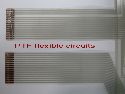
Polymer Thick Film (PTF) flexible circuits are manufactured by screen-printing conductive ink onto flexible substrates such as PET (Polyethylene terephthalate). It can be single layer or multi-layers circuit by further screen-printing dielectric materials as insulating layer and applying through-hole technologies.
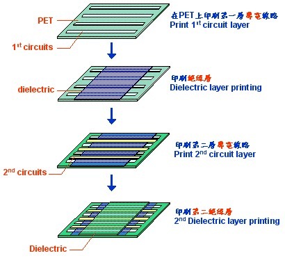
The manufacturing process for two layer circuits of PTF:
Step 1, Print first circuits on PET flexible circuits. The material of circuit usually is silver and carbon combination ink.
Step 2, Print the dielectric layer to cover the 1st circuits. The usual dielectric material is UV ink.
Step 3, Print the second circuits on the dielectric layer.
Step 4, Print the final dielectric layer to cover all the circuits.
The Benefit of PTF
- Save money and good to environment: PTF circuits use additive printing with silver and carbon inks through screen printing. No need plating and no population concern. The PET substrate is commonly applying the less costly than materials traditionally used in FPC (Flexible Printing Circuit) manufacturing.
- Shorter lead-time: Since the manufacturing process is more simple than FPC. So its lead-time will be shorter than FPC.
The Disadvantage of PTF
- No shape angle bending: No recommend bending the FPC with shape angle to prevent the circuit traces breaking.
- Fine pitch circuits limit: The regular circuit pattern width/space is 20mils (0.5mm) and the minimum circuit pattern width/space is 5mils (0.127mm) but is limited. (Note: The minimum circuit pattern width/space for FPC is 3mils)

0 意見:
張貼留言